Cudy AP1300 Outdoor and OpenWRT: Difference between revisions
mNo edit summary |
|||
| Line 52: | Line 52: | ||
The WR1300 V2 & V3 Firmware should work, right?[[File:Cudy AP1300 Firmware Upgrade Attempt with WR1300 v2 and v3 Intermediary Firmware FAILURE.png|alt=Cudy AP1300 Firmware Upgrade Attempt with WR1300 v2 and v3 Intermediary Firmware FAILURE|thumb|Cudy AP1300 Firmware Upgrade Attempt with WR1300 v2 and v3 Intermediary Firmware FAILURE|none]]Oh, well. Time to break out the screw driver. | The WR1300 V2 & V3 Firmware should work, right?[[File:Cudy AP1300 Firmware Upgrade Attempt with WR1300 v2 and v3 Intermediary Firmware FAILURE.png|alt=Cudy AP1300 Firmware Upgrade Attempt with WR1300 v2 and v3 Intermediary Firmware FAILURE|thumb|Cudy AP1300 Firmware Upgrade Attempt with WR1300 v2 and v3 Intermediary Firmware FAILURE|none]]Oh, well. Time to break out the screw driver. | ||
=== Taking the Dang Thing Apart (with a minor secret) === | ===Taking the Dang Thing Apart (with a minor secret)=== | ||
There are two obvious screws and two not so obvious nuts. | There are two obvious screws and two not so obvious nuts. | ||
| Line 59: | Line 59: | ||
The entire unit should then slide out (with some resistance because of the o-rings around the RP-SMA Connector brass threads (PS: Don't loose them) | The entire unit should then slide out (with some resistance because of the o-rings around the RP-SMA Connector brass threads (PS: Don't loose them) | ||
=== Upgrading the Firmware === | ===Upgrading the Firmware=== | ||
In the same fashion as the Cudy AP3000 Indoor, the Pin Hole Headers for TTL / Serial communication is covered by the heatsink. No big deal, use the special devices noted in this article: [[Cudy AP3000 Indoor AKA Jupiter 2 and OpenWRT|Cudy AP3000 Indoor AKA Jupiter 2 and OpenWRT - Wiki.TerraBase.info]] Otherwise, unscrew the heatsink, solder in some pins on the bottom of the PCB so the heatsink can go back in place, then after programming be prepared to maybe trim them, but odds are they'll fit into the enclosure. | In the same fashion as the Cudy AP3000 Indoor, the Pin Hole Headers for TTL / Serial communication is covered by the heatsink. No big deal, use the special devices noted in this article: [[Cudy AP3000 Indoor AKA Jupiter 2 and OpenWRT|Cudy AP3000 Indoor AKA Jupiter 2 and OpenWRT - Wiki.TerraBase.info]] Otherwise, unscrew the heatsink, solder in some pins on the bottom of the PCB so the heatsink can go back in place, then after programming be prepared to maybe trim them, but odds are they'll fit into the enclosure. | ||
[[File:Cudy AP1300 Pin Headers under Heatsink.jpg|alt=Cudy AP1300 Pin Headers under Heatsink|none|thumb|Cudy AP1300 Pin Headers under Heatsink]] | [[File:Cudy AP1300 Pin Headers under Heatsink.jpg|alt=Cudy AP1300 Pin Headers under Heatsink|none|thumb|Cudy AP1300 Pin Headers under Heatsink]] | ||
Pins left to right, with the RP-SMA Connectors to the right and the Ethernet Jack to the left; | Pins left to right, with the RP-SMA Connectors to the right and the Ethernet Jack to the left; | ||
* TX | *TX | ||
* RX | *RX | ||
* GND | *GND | ||
* 3.3 + Volts | *3.3 + Volts | ||
== ...as of 04.2025 NO Solution. U-Boot is hamstrung in that all it will do is TFTP a recovery file named recovery.bin and will attempt to 'install' that. InitRAMFS files don't load or run AND the TTL / Serial connection is wonky as all heck, just cannot predict its functionality, it vacillates between working, printing gibberish, or doing nothing at all. == | |||
Latest revision as of 00:38, 9 April 2025
...OK kiddos, buckle up. Can the AP1300 run OpenWRT? Seems like it can.
Evaluation (See below links for a comparison)
- Cudy AP1300 Outdoor: https://techinfodepot.shoutwiki.com/wiki/Cudy_AP1300_Outdoor#Flashing_OpenWrt
- Cudy WR1300 v3: https://techinfodepot.shoutwiki.com/wiki/Cudy_WR1300_v3 (v2 and v3 are the same, confirmed by the fact that Cudy's "Intermediary Firmware" is in the same file, WR1300+V2-V3.zip)
Notice how the CPU link is the same for both? The AP1300 has an MT7621DAT and the WR1300 has the MT7621AT
What does ChatGPT have to say about this?
Here is a comparison table of the MediaTek MT7621AT and MT7621DAT SoCs based on all publicly documented differences and similarities;

Feature / Category		MT7621AT							MT7621DAT
CPU Architecture		MIPS 1004Kc Dual-Core @ 880 MHz		MIPS 1004Kc Dual-Core @ 880 MHz
CPU Cores				2									2
Process Node			28nm								28nm
Cache					32KB I-Cache  32KB D-Cache per core	Same
L2 Cache				256KB shared						Same
Memory Support			DDR2 / DDR3 up to 1GB				Same
PCIe Support			2× PCIe 2.0 (1×1 lane, 1×2 lanes)	Same
Switch					5-Port Gigabit Ethernet switch		Same
GMAC					2× RGMII Gigabit MACs				Same
USB					1× USB 3.0 Host, 1× USB 2.0 Host		Same
NAND/NOR Flash			NAND (via EBU) and NOR support		Same
SATA					Yes (1× SATA 2.0)					Same
Crypto Engine			Yes (IPSec, AES, 3DES, SHA)			Same
Hardware NAT			Yes									Yes
Target Devices			Consumer Routers, APs				OEM-Specific Variants (functionally same)
Difference				Mass-market, more common in retail	Same SoC, different labeling for OEM

Clarification;
MT7621DAT is a functionally identical variant of MT7621AT. The "D" in the part number is believed to represent a packaging, sourcing, or binning difference, and there are no architectural or functional changes between the two according to all known sources, including hardware dumps, OpenWRT device trees, and boot logs.

📚Source references;
MediaTek MT7621 SoC data sheets (partial, not public in full form)

OpenWRT wiki – MT7621 platform
Bootloader reports from various devices (GL.iNet, Mikrotik, etc.)
Community decompilation and board testing (e.g. boot logs from U-Boot showing SoC IDs)
Wow, in a rare lucid moment for ChatGPT creates what seems to be something that passes for factual and accurate. Double checking it manually confirms it.
Where's the Firmware?
Nope (seems like it should be though): https://mirror-03.infra.openwrt.org/releases/24.10.0/targets/mediatek/
Yup (of course, it's obvious): https://mirror-03.infra.openwrt.org/releases/24.10.0/targets/ramips/ (mt7621 Directory)
Historical Note: RAMIPS = Ralink, which was the name of the entity before MediaTek bought it.
Wait! What about the "Intermediary Firmware" that Cudy makes? That should make upgrading to OpenWRT firmware easy!
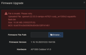
The WR1300 V2 & V3 Firmware should work, right?

Oh, well. Time to break out the screw driver.
Taking the Dang Thing Apart (with a minor secret)
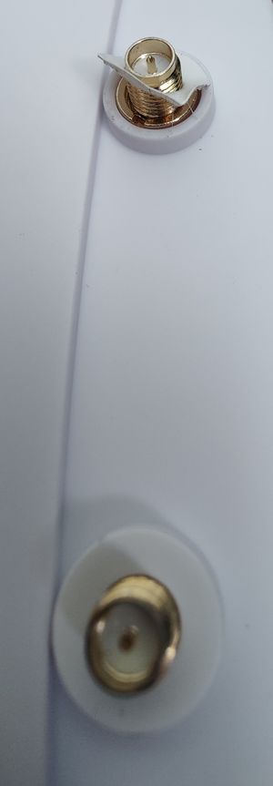
There are two obvious screws and two not so obvious nuts.
The "nuts' are used to secure the RP-SMA Threaded Connectors at the top of the device. They're covered by white 'doughnut stickers'. Peel those off and unscrew the brass 'slotted nuts'.

The entire unit should then slide out (with some resistance because of the o-rings around the RP-SMA Connector brass threads (PS: Don't loose them)
Upgrading the Firmware
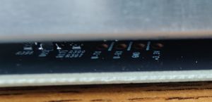
In the same fashion as the Cudy AP3000 Indoor, the Pin Hole Headers for TTL / Serial communication is covered by the heatsink. No big deal, use the special devices noted in this article: Cudy AP3000 Indoor AKA Jupiter 2 and OpenWRT - Wiki.TerraBase.info Otherwise, unscrew the heatsink, solder in some pins on the bottom of the PCB so the heatsink can go back in place, then after programming be prepared to maybe trim them, but odds are they'll fit into the enclosure.

Pins left to right, with the RP-SMA Connectors to the right and the Ethernet Jack to the left;
- TX
- RX
- GND
- 3.3 + Volts