[[File:GL iNet GL MV1000W Brume SystemBoard with TTL Serial Pin Headers courtesy of OpenWRT.org.jpg|alt=GL-iNet GL-MV1000W Brume SystemBoard with TTL-Serial Pin Headers (courtesy of OpenWRT.org).jpg|thumb|GL-iNet GL-MV1000W Brume SystemBoard with TTL-Serial Pin Headers (courtesy of OpenWRT.org).jpg]]
[[File:GL iNet GL MV1000W Brume SystemBoard with TTL Serial Pin Headers courtesy of OpenWRT.org.jpg|alt=GL-iNet GL-MV1000W Brume SystemBoard with TTL-Serial Pin Headers (courtesy of OpenWRT.org).jpg|thumb|GL-iNet GL-MV1000W Brume SystemBoard with TTL-Serial Pin Headers (courtesy of OpenWRT.org).jpg]]
* '''Connect Serial / TTL Port (optional, requires 'disassembly' (see Disassembly Section);'''
*'''Connect Serial / TTL Port (optional, requires 'disassembly' (see Disassembly Section);'''
** The Serial / TTL Header is just there. 3 Pins, already on the System Board (near bottom of image to the right of the grayish rectangle (Ethernet Ports) and just to the left of the silver rectangle(s) (USB A and USB C Ports)) with the 'PIN Legend' printed on the SystemBoard (GND nearest the closest edge, then RX (Receive), and TX (Transmit)).
**The Serial / TTL Header is just there. 3 Pins, already on the System Board (near bottom of image to the right of the grayish rectangle (Ethernet Ports) and just to the left of the silver rectangle(s) (USB A and USB C Ports)) with the 'PIN Legend' printed on the SystemBoard (GND nearest the closest edge, then RX (Receive), and TX (Transmit)).
** Serial Port Settings for PuTTY, SecureCRT, etc: 115200, 8, None, 1, No (That's Baud Rate, Data Bits, Parity, Stop Bits, Flow Control).
**Serial Port Settings for PuTTY, SecureCRT, etc: 115200, 8, None, 1, No (That's Baud Rate, Data Bits, Parity, Stop Bits, Flow Control).
** Hook it up, plug it in, and OpenWRT is ready to go. Job done! Nope (but it really is OpenWRT that it boots to, just a special custom 'flavor' from GL-iNet)
**Hook it up, plug it in, and OpenWRT is ready to go. Job done! Nope (but it really is OpenWRT that it boots to, just a special custom 'flavor' from GL-iNet)
* Configure Computer with IP Address of 192.168.1.2 (should be able to do anything on the 192.168.1.X subnet). The Device's IP Address will be 192.168.1.1
*Configure Computer with IP Address of 192.168.1.2 (should be able to do anything on the 192.168.1.X subnet). The Device's IP Address will be 192.168.1.1
* "Official Instructions" state: WAN port cannot be connected (turns out that's not accurate, tested, and it can be connected)
*"Official Instructions" state: WAN port cannot be connected (turns out that's not accurate, tested, and it can be connected)
====Installing a New Install of OpenWRT from Command Prompt of the Device's OEM Version of OpenWRT is not Possible====
====Installing a New Install of OpenWRT from Command Prompt of the Device's OEM Version of OpenWRT is not Possible====
Line 76:
Line 76:
OK, tirade over.
OK, tirade over.
*...don't even need to press it, although installation of OpenWRT can be done from U-Boot on this device in a similar manner to the Linksys EA8500: https://openwrt.org/toh/linksys/ea8500?s[]=ea8500. It's easier using the method in the previous section
*...don't even need to press it, although installation of OpenWRT can be done from U-Boot on this device in a similar manner to the Linksys EA8500: https://openwrt.org/toh/linksys/ea8500?s[]=ea8500. It's easier using the method in the previous section.
=== Disassembly ===
=== "Upgrading" / Expanding the 'Disk Drive' (built in MMC (Multi-Media Card), not the SD Card Slot) ===
Start off with this, so you can see what's going on;
* <code>opkg update</code>
* <code>opkg install lsblk blkid</code>
* Type: lsblk[[File:GL iNet GL MV1000W Brume 8 GB MMC.png|alt=GL-iNet GL-MV1000W Brume - 8 GB MMC|left|thumb|GL-iNet GL-MV1000W Brume - 8 GB MMC]]See that very last item?: mmcblk1, 7.3 GB in size A router with 8 GB of built in storage? Ever see that? Well, it has to be "earned" Go ahead, look and see the available space in the LuCI GUI. 7 some odd GB available? Nope. 100.xx MiB? WTF?!?! Why didn't they make that space available by default? The answer is unknown. Is there a way to take advantage of it? Sure there is. There's even instructions on the OpenWRT.org webpage for this device. But don't follow them (even if you can understand what the heck is written) as it is a complete kludge that doesn't do justice to the device.
Below is the rough draft as there isn't time today to check and edit it and add commentary, but it is fairly accurate;
** For the Device that was found (usually /dev/sda)
*** Edit
*** Enable
*** Mount point: root filesystem (/)
*** Follow the "Root Preparation" instructions
*** REBOOT
* System, Mount Points, Mount Points: ...and it should show that the root ( / ) Directory is on /dev/sda1 (the USB Flash Drive)
* opkg "all the same Packages as above"
* Reboot. After rebooting, full access to do all that is necessary on the built in MMC device will be possible (not so if the router was booted to the MMC device)
* lsblk (just to see everything)
* umount /rom (isn't needed right now, or ever really after booting)
* No No, just kidding, don't do it: wipefs -a /dev/mmcblk1 (if deleted, OpenWRT will need to be installed again, with the same small size partition)
* cfdisk /dev/mmcblk1 (for now, just to see the layout of things and confirm that 7.2 G of space is waiting there to be used)
* And now: Highlight the /dev/mmcblk1p2 Partition, select Resize and either max it out or set it to 6.0 GB, leaving space for a Swap Partition (recommended, but not covered here), Write it (confirming with "yes"), Exit. This only resizes the partition. Next step is to resize the File System to take advantage of the new Partition size (and now it is understood why EXT4 was used as the file system, not SquashFS, etc.)
* umount /rom (yes, again, but a reboot occured so it remounted)
* resize2fs /dev/mmcblk1p2 (didn't work, but it does give you the 'CHKDSK' command that must be run first, so it can be copied and pasted without typing or e2fsck -f /dev/mmcblk1p2)
* lsblk (yummy, now 7GB or whatever size was decided upon, much larger than the ~102 MiB size that left all that tantalizing space unused)
* Remove the USB Flash Drive, Reboot
* Good to go! Now booted from the internal MMC, using all (or as much as was wanted) the space available
* lsblk (to check it)
Expanding the drive where OpenWRT was installed was the key. If the MMC was wiped and the partition size was increased, OpenWRT would have to be reinstalled which would take it down to the smaller size. Of course one could copy all the files back from the USB Flash Drive to the MMC after its size was increased (as that's the way the USB Flash drive was created).
=== Wireless ===
This has to be installed manually;
* opkg update
* opkg install kmod-rtl8xxxu rtl8192eu-firmware
* Reboot (give it a minute or so as this reboot will take a few extra seconds the first time after installing the wireless software)
* Wireless is now available.
<br />
===Disassembly===
Remove the two rubber feet closest to the front. Unscrew the two screws that are now visible. Start at the back, above the USB Ports, and gently pry up, working around to the front on both sides.
Remove the two rubber feet closest to the front. Unscrew the two screws that are now visible. Start at the back, above the USB Ports, and gently pry up, working around to the front on both sides.
Revision as of 21:09, 19 August 2024
...a great little device that doesn't seem to be made anymore: GL-iNet GL-MV1000W
Dual 1 GHz CPUs
1 GB of RAM
micro SD Card Slot
PLUS
Small Form Factor
USB C Power
3 Port Switch
Antennas can be removed and replaced with RP-SMA Connectors fairly easily
8 GB MMC Storage Built in (but it has to be "earned")
GL-iNet GL-MV1000W Brume SystemBoard with TTL-Serial Pin Headers (courtesy of OpenWRT.org).jpg
Connect Serial / TTL Port (optional, requires 'disassembly' (see Disassembly Section);
The Serial / TTL Header is just there. 3 Pins, already on the System Board (near bottom of image to the right of the grayish rectangle (Ethernet Ports) and just to the left of the silver rectangle(s) (USB A and USB C Ports)) with the 'PIN Legend' printed on the SystemBoard (GND nearest the closest edge, then RX (Receive), and TX (Transmit)).
Serial Port Settings for PuTTY, SecureCRT, etc: 115200, 8, None, 1, No (That's Baud Rate, Data Bits, Parity, Stop Bits, Flow Control).
Hook it up, plug it in, and OpenWRT is ready to go. Job done! Nope (but it really is OpenWRT that it boots to, just a special custom 'flavor' from GL-iNet)
Configure Computer with IP Address of 192.168.1.2 (should be able to do anything on the 192.168.1.X subnet). The Device's IP Address will be 192.168.1.1
"Official Instructions" state: WAN port cannot be connected (turns out that's not accurate, tested, and it can be connected)
Installing a New Install of OpenWRT from Command Prompt of the Device's OEM Version of OpenWRT is not Possible
...but to try it out and see;
After connecting to the TTL / Serial Port, plug a cable into the Internet Ethernet Port.
opkg install wget (the BusyBox version of wget won't work with modern TLS / SSL)
wget https://downloads.openwrt.org/releases/23.05.0/targets/mvebu/cortexa53/openwrt-23.05.0-mvebu-cortexa53-glinet_gl-mv1000-ext4-sdcard.img.gz, or whatever the latest version of OpenWRT is. And no, the "SD Card" version doesn't have to be installed on an SD Card (funny thing is that the large internal storage on this device is based on an MMC (Multi-Media Card) that is soldered to the SystemBoard. The important part about which version (EXT4, InitRAMFS, or SquashFS) is that it uses the EXT4 file system which will be important later (part of the "earning" the 8 GB of storage thing). There is also not going to be a debate as to which file system is 'kinder' to Solid State Storage as only EXT 4 will be able to take FULL advantage of the 8 GB of storage (in a non-convoluted way).
sysupgrade /WhatEverImageName.img See, it won't work as GL-iNet decided they weren't going to allow it (odd, since they seem so OpenWRT friendly compared to most manufacturers).
This was included as a long, passive agressive, 'Implicitish' (#Implicitish, come on, only 5 other instance of this word on the internet according to Google as of mid TwentyTwoFour) commentary for the person that decided to include the rather useless Upgrading OpenWrt Section for this device on the OpenWRT.org website.
Installing a New / Fresh Install of OpenWRT from the Built in Boot Loader GUI
The timing on this one is a bit tough. Confirmation can be seen if you have a TTL / Serial connection to the device via the Pin Header where it will show on the screen;
Reset button is pressed for: "6 or 7"* HTTP Server is starting at IP: 192.168.1.1

* "6 or 7": Usually 7 will be displayed even if the Reset Button is released at 6 (as it should be)
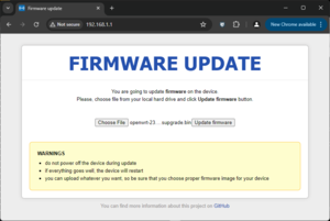
GL-iNet GL-MV1000W Brume - Firmware Update Web PagePlug the device in AND Hold the reset Button (firmly), just watch for the practice the first time;
All three lights on the front light up (Power, WiFi, and VPN)
All three lights on the front turn off
The Power Light turns on
The WiFi Light turns on
Let go of the Reset Button
GL-iNet GL-MV1000W Brume - Successful Upgrade
At this point use a web browser to navigate to 192.168.1.1 where the "Firmware update" Page should be seen. Also, the official documentation on the OpenWRT.org website uses the incorrect title for one of the lights on the installation instructions.
If connected with a Serial / TTL device: Watch the "count-up", 1, 2, 3, 4, 5, 6, and before 7, let go of the Reset Button
Installing a New Install of OpenWRT from U-Boot (plus a Tirade)
After connecting to the TTL / Serial Port, plug a cable into the Internet Ethernet Port (again), get ready to press the 'gl' key. Wait! What? The actual message you will see is;
Hit "gl" key to stop booting in X seconds. (no kidding, that's the actual message)
First that's gl, as in g+lowercase"L" (l as in Larry, thank English Language and modern computer for making l I and 1 (That's a lower case l, Upper Case I (as in Insulting), and the number One) so wonderfully, perfectly, exactly the same. Seriously!?!?!?
OK, gl key, let's see, f1, f2, ..., f12... Hmmm. Crap, no g1, no, gl.
Hit? Did you mean Press?
G and L are two "keys", not one "key"
Stop Booting? No! I need a Boot Loader command prompt. Boot to that.
It is absolutely stupefying a sentence that is less than 10 characters long have so many issues. Here's the right way gentlement;
Press the G Key and then the L Key to enter the U-Boot Command Interface. (was that so difficult?)
OK, tirade over.
...don't even need to press it, although installation of OpenWRT can be done from U-Boot on this device in a similar manner to the Linksys EA8500: https://openwrt.org/toh/linksys/ea8500?s%5B%5D=ea8500. It's easier using the method in the previous section.
"Upgrading" / Expanding the 'Disk Drive' (built in MMC (Multi-Media Card), not the SD Card Slot)
Start off with this, so you can see what's going on;
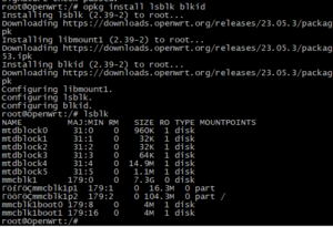
opkg update
opkg install lsblk blkid
Type: lsblkGL-iNet GL-MV1000W Brume - 8 GB MMCSee that very last item?: mmcblk1, 7.3 GB in size A router with 8 GB of built in storage? Ever see that? Well, it has to be "earned" Go ahead, look and see the available space in the LuCI GUI. 7 some odd GB available? Nope. 100.xx MiB? WTF?!?! Why didn't they make that space available by default? The answer is unknown. Is there a way to take advantage of it? Sure there is. There's even instructions on the OpenWRT.org webpage for this device. But don't follow them (even if you can understand what the heck is written) as it is a complete kludge that doesn't do justice to the device.
Below is the rough draft as there isn't time today to check and edit it and add commentary, but it is fairly accurate;
System, Mount Points, Mount Points: ...and it should show that the root ( / ) Directory is on /dev/sda1 (the USB Flash Drive)
opkg "all the same Packages as above"
Reboot. After rebooting, full access to do all that is necessary on the built in MMC device will be possible (not so if the router was booted to the MMC device)
lsblk (just to see everything)
umount /rom (isn't needed right now, or ever really after booting)
No No, just kidding, don't do it: wipefs -a /dev/mmcblk1 (if deleted, OpenWRT will need to be installed again, with the same small size partition)
cfdisk /dev/mmcblk1 (for now, just to see the layout of things and confirm that 7.2 G of space is waiting there to be used)
And now: Highlight the /dev/mmcblk1p2 Partition, select Resize and either max it out or set it to 6.0 GB, leaving space for a Swap Partition (recommended, but not covered here), Write it (confirming with "yes"), Exit. This only resizes the partition. Next step is to resize the File System to take advantage of the new Partition size (and now it is understood why EXT4 was used as the file system, not SquashFS, etc.)
umount /rom (yes, again, but a reboot occured so it remounted)
resize2fs /dev/mmcblk1p2 (didn't work, but it does give you the 'CHKDSK' command that must be run first, so it can be copied and pasted without typing or e2fsck -f /dev/mmcblk1p2)
lsblk (yummy, now 7GB or whatever size was decided upon, much larger than the ~102 MiB size that left all that tantalizing space unused)
Remove the USB Flash Drive, Reboot
Good to go! Now booted from the internal MMC, using all (or as much as was wanted) the space available
lsblk (to check it)
Expanding the drive where OpenWRT was installed was the key. If the MMC was wiped and the partition size was increased, OpenWRT would have to be reinstalled which would take it down to the smaller size. Of course one could copy all the files back from the USB Flash Drive to the MMC after its size was increased (as that's the way the USB Flash drive was created).
Wireless
This has to be installed manually;
opkg update
opkg install kmod-rtl8xxxu rtl8192eu-firmware
Reboot (give it a minute or so as this reboot will take a few extra seconds the first time after installing the wireless software)
Wireless is now available.
Disassembly
Remove the two rubber feet closest to the front. Unscrew the two screws that are now visible. Start at the back, above the USB Ports, and gently pry up, working around to the front on both sides.