Cudy AP3000 Indoor AKA Jupiter 2 and OpenWRT: Difference between revisions
| Line 12: | Line 12: | ||
No details here on what is needed for that as there is plenty of information out there. This website has some pictures: https://eko.one.pl/forum/viewtopic.php?id=24096 Oh, and great spot for the vias to solder in some pins, right? Well good news is that there is lots of space if one solders the pins on the backside of the PCB. | No details here on what is needed for that as there is plenty of information out there. This website has some pictures: https://eko.one.pl/forum/viewtopic.php?id=24096 Oh, and great spot for the vias to solder in some pins, right? Well good news is that there is lots of space if one solders the pins on the backside of the PCB. | ||
== Pins / Holes for Serial / TTY == | ==Pins / Holes for Serial / TTY== | ||
Here's another really cool thing. The Pin Headers for the TTY / Serial communication are covered by a heat sink (on the top of the PCB) and a base plate (on the bottom of the PCB). It has been noticed that there is a minor design difference on some models where the Header Pin Holes on some models are visible because of a smaller base plate. Others have a base plate that covers the holes. | Here's another really cool thing. The Pin Headers for the TTY / Serial communication are covered by a heat sink (on the top of the PCB) and a base plate (on the bottom of the PCB). It has been noticed that there is a minor design difference on some models where the Header Pin Holes on some models are visible because of a smaller base plate. Others have a base plate that covers the holes. | ||
The Header Pin Holes from the | The Header Pin Holes from the left, labeled from the edge of the PCB closest to the holes (which is to the right of the picture) or just look at the picture of the top of the PCB (at the bottom of the page) with the Header Pin Holes labeled with a screen printing. | ||
[[File:Cudy AP3000 (Indoor Jupiter 2) TTY Serial Headers Bottom with Header Clips.jpg|alt=Cudy AP3000 (Indoor Jupiter 2) TTY Serial Headers Bottom with Header Clips|left|thumb|Cudy AP3000 (Indoor Jupiter 2) TTY Serial Headers Bottom with Header Clips]] | [[File:Cudy AP3000 (Indoor Jupiter 2) TTY Serial Headers Bottom with Header Clips.jpg|alt=Cudy AP3000 (Indoor Jupiter 2) TTY Serial Headers Bottom with Header Clips|left|thumb|Cudy AP3000 (Indoor Jupiter 2) TTY Serial Headers Bottom with Header Clips]] | ||
<br /> | <br /> | ||
* VCC / 3.3 Volts + | *VCC / 3.3 Volts + | ||
* GND / Negative | *GND / Negative | ||
* RX | *RX | ||
* TX (the square solder pad) | *TX (the square solder pad) | ||
Oh, and notice the little "PCB Test Clips" / "Test Points" / "Through Hole Loops" (various names they're referred to as). No solder needed, works great. Why not just solder in some pins? Remember, if you've got a model that has the bigger base plate, they'll need to be unsoldered too. Clip Leads? In the middle of the board. Difficult if not impossible. Some spring "grabber" style might work if there's something on the other side to grab onto. | |||
* https://www.amazon.com/dp/B0BC6CBDYY?ref_=ppx_hzsearch_conn_dt_b_fed_asin_title_2 (thankfully out of stock as of the writing of this) | |||
* https://www.ebay.com/itm/324836665545 (for bigger holes, not these, just noting this one so it is known there are different sizes)<br />And don't forget, it'll probably be wiser to do all of this from the bottom and gently screw the heatsink back in place over the SoCs so nothing melts while the upgrade is taking place. | |||
==Hardware Setup== | ==Hardware Setup== | ||
Revision as of 02:50, 8 April 2025
Installing OpenWRT on a Cudy AP3000 (Indoor, AKA the Jupiter 2)
Overview
How about following the instructions on the OpenWRT.org website for a similar device (with the EXACT same CPU, WiFi, etc.): https://openwrt.org/toh/cudy/tr3000
Nope. Sadly Cudy doesn't make an InitRAMFS BIN file for the AP3000 (Indoor), even though the file for the AP3000 would work it weren't for their gosh darned 'security feature' of having a signed file. Side note: Is there really an instance where this has helped an end user, or is it about manufacturer control?
Anyway, that's out, so what about a TTY / Serial session? Not a chance. Why? Well: ethernet@15100000 Waiting for PHY auto negotiation to complete......... TIMEOUT ! It appears that the u-boot image is busted in that the Ethernet Interface does NOT work. It shows as 'active', but no link light on a switch and it just doesn't work. Blame this guy: U-Boot 2022.07-rc3 (Sep 01 2023 - 07:34:59 +0000), Build: jenkins-AP3000-19 (well, either he did it, didn't know what he did, or was told to do it, in any instance, is doesn't help the end owner of the device that wants OpenWRT installed)
But there is a solution: TTY / Serial
No details here on what is needed for that as there is plenty of information out there. This website has some pictures: https://eko.one.pl/forum/viewtopic.php?id=24096 Oh, and great spot for the vias to solder in some pins, right? Well good news is that there is lots of space if one solders the pins on the backside of the PCB.
Pins / Holes for Serial / TTY
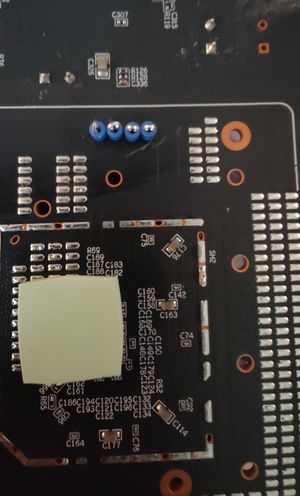
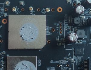
Here's another really cool thing. The Pin Headers for the TTY / Serial communication are covered by a heat sink (on the top of the PCB) and a base plate (on the bottom of the PCB). It has been noticed that there is a minor design difference on some models where the Header Pin Holes on some models are visible because of a smaller base plate. Others have a base plate that covers the holes.
The Header Pin Holes from the left, labeled from the edge of the PCB closest to the holes (which is to the right of the picture) or just look at the picture of the top of the PCB (at the bottom of the page) with the Header Pin Holes labeled with a screen printing.

- VCC / 3.3 Volts +
- GND / Negative
- RX
- TX (the square solder pad)
Oh, and notice the little "PCB Test Clips" / "Test Points" / "Through Hole Loops" (various names they're referred to as). No solder needed, works great. Why not just solder in some pins? Remember, if you've got a model that has the bigger base plate, they'll need to be unsoldered too. Clip Leads? In the middle of the board. Difficult if not impossible. Some spring "grabber" style might work if there's something on the other side to grab onto.
- https://www.amazon.com/dp/B0BC6CBDYY?ref_=ppx_hzsearch_conn_dt_b_fed_asin_title_2 (thankfully out of stock as of the writing of this)
- https://www.ebay.com/itm/324836665545 (for bigger holes, not these, just noting this one so it is known there are different sizes)
And don't forget, it'll probably be wiser to do all of this from the bottom and gently screw the heatsink back in place over the SoCs so nothing melts while the upgrade is taking place.
Hardware Setup
- Target Device: Cudy AP3000 (MediaTek MT7981 SoC)
- Access: Serial console via FTDI or CH340 USB-UART adapter
- Host OS: Rocky Linux 9
- Tools used: `sx`, `loadx`, `iminfo`, `bootm`, `LuCI`
U-Boot Setup and Memory Layout
From `bdinfo` output:
| Item | Value |
|---|---|
| DRAM Start | 0x40000000 |
| DRAM Size | 0x20000000 (512 MiB) |
| U-Boot Relocated Addr | ~0x5ff38000 |
| Reserved Region | 0x5f7fb170 – 0x5fffffff |
Safe RAM Load Addresses
| Label | Address | Offset (from 0x40000000) | Status |
|---|---|---|---|
| Known Good | 0x42000000 | 32 MB | ✅ SAFE |
| Default (`loadaddr`) | 0x46000000 | 96 MB | ✅ OK (tight) |
| High (bad) | 0x48000000 | 128 MB | ❌ Caused crash on decompression |
Uploading OpenWRT initramfs FIT image
In U-Boot (via serial)
The first three items are just a 'safety precaution', as it was observed in some circumstances when trying to use a different load command that the system would just boot in the middle of the file transfer.
setenv bootcmd
setenv bootdelay -1
saveenv

loadx 0x42000000
On Host PC
Assuming `/dev/ttyUSB0` is your serial device:
sx -vv WhatEverNameOfFile.bin < /dev/ttyUSB0 > /dev/ttyUSB0...but first download the "InitRAMFS" File from OpenWRT: https://downloads.openwrt.org/releases/24.10.0/targets/mediatek/filogic/ (look for Cudy AP3000, without the 'outdoor' reference, but notice it is the same size file, so probably the same file with a different name)
Image Inspection in U-Boot
iminfo 0x42000000Result (partial):
- FIT image detected
- Kernel: LZMA compressed, load/entry address: 0x48000000
- initrd and FDT present and hash-verified
Booting the Image
bootm 0x42000000This succeeded once the image was loaded at `0x42000000` — avoiding the earlier problem of overlapping the kernel decompress target address `0x48000000`.
Permanent Installation
After booting into OpenWRT RAM (initramfs):
- Connect to LuCI via web browser (default IP: 192.168.1.1)
- Navigate to System → Backup / Flash Firmware
- Upload the permanent OpenWRT SquashFS image (`*-squashfs-sysupgrade.bin`) (see above link, and get the SquashFS File)
- Choose "Do not keep settings"
- Flash the image and reboot
Final Result
OpenWRT was permanently installed on flash using the SquashFS image, without requiring a network or TFTP boot. All steps were performed over a serial console with full visibility into memory layout and safe load addresses.
Notes
- Always verify the image format (`iminfo`) before booting.
- Do not load images to `0x48000000` if that is also the decompress target.
- To make this repeatable, avoid saving `bootcmd` unless a custom autoboot is configured.
